3D Lighting on 2D Pixels: Lighting-Aware Normal Estimation
Background
I recently came across a pixel-art lighting tool called Pixel Art Lighter shared by @moonfell_rpg. The results looked genuinely impressive, so I dug into it.
Note that the tool is currently web-only. It's open source under MIT by way of being distributed with the web page, but there's no GitHub repo (the author replied that the tool lives in the same repo as his game, so it's not convenient to publish).
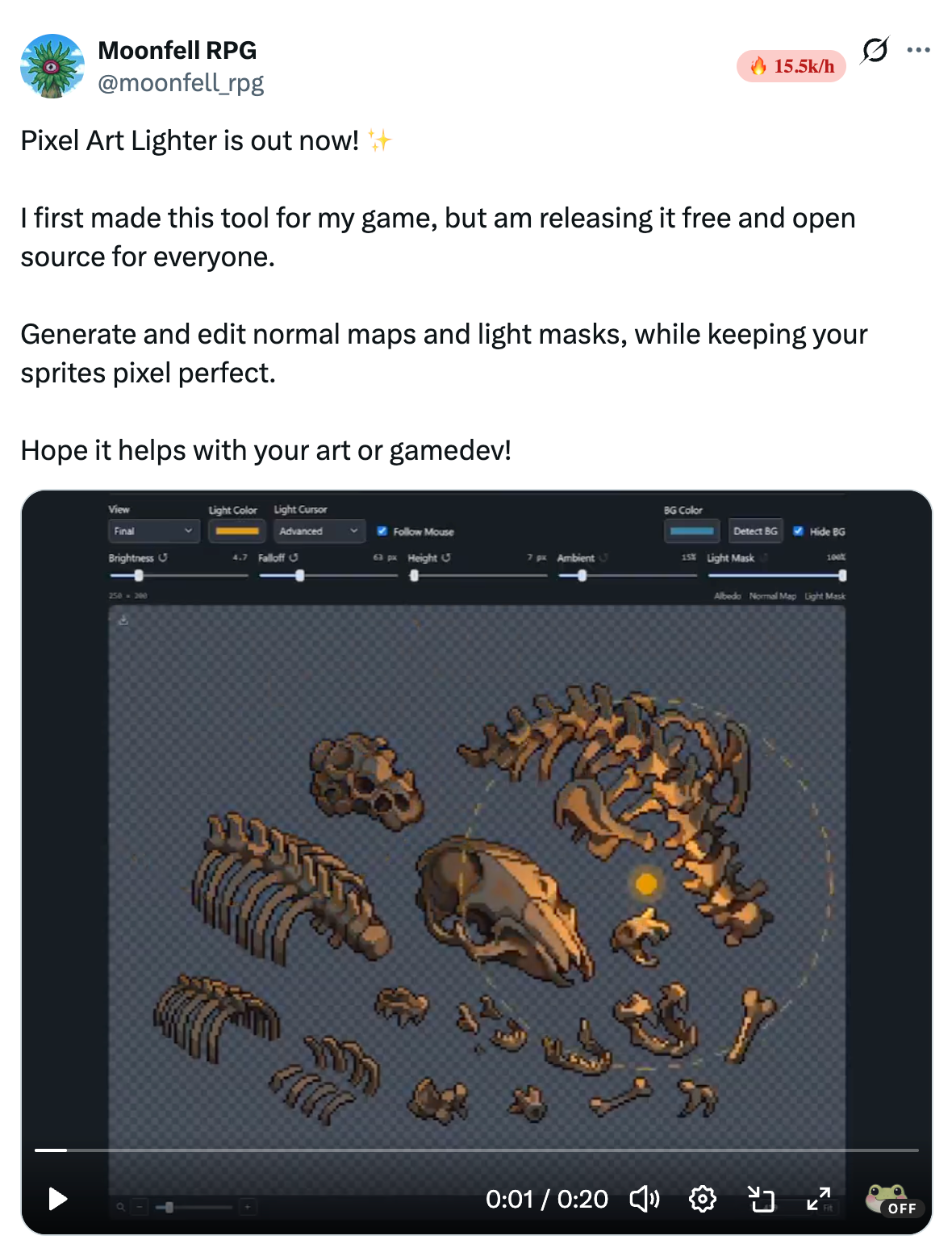
If you've worked with 3D modeling or game engines, you may already know the principle behind it: normal maps.
A quick explanation: a normal map records a facing direction for each pixel, with the RGB channels representing the rightward, upward, and out-of-screen components. Once you have directions, a simple Lambert model tells you how much each pixel faces the light, giving you dynamic lighting:

Traditional normal-map generation
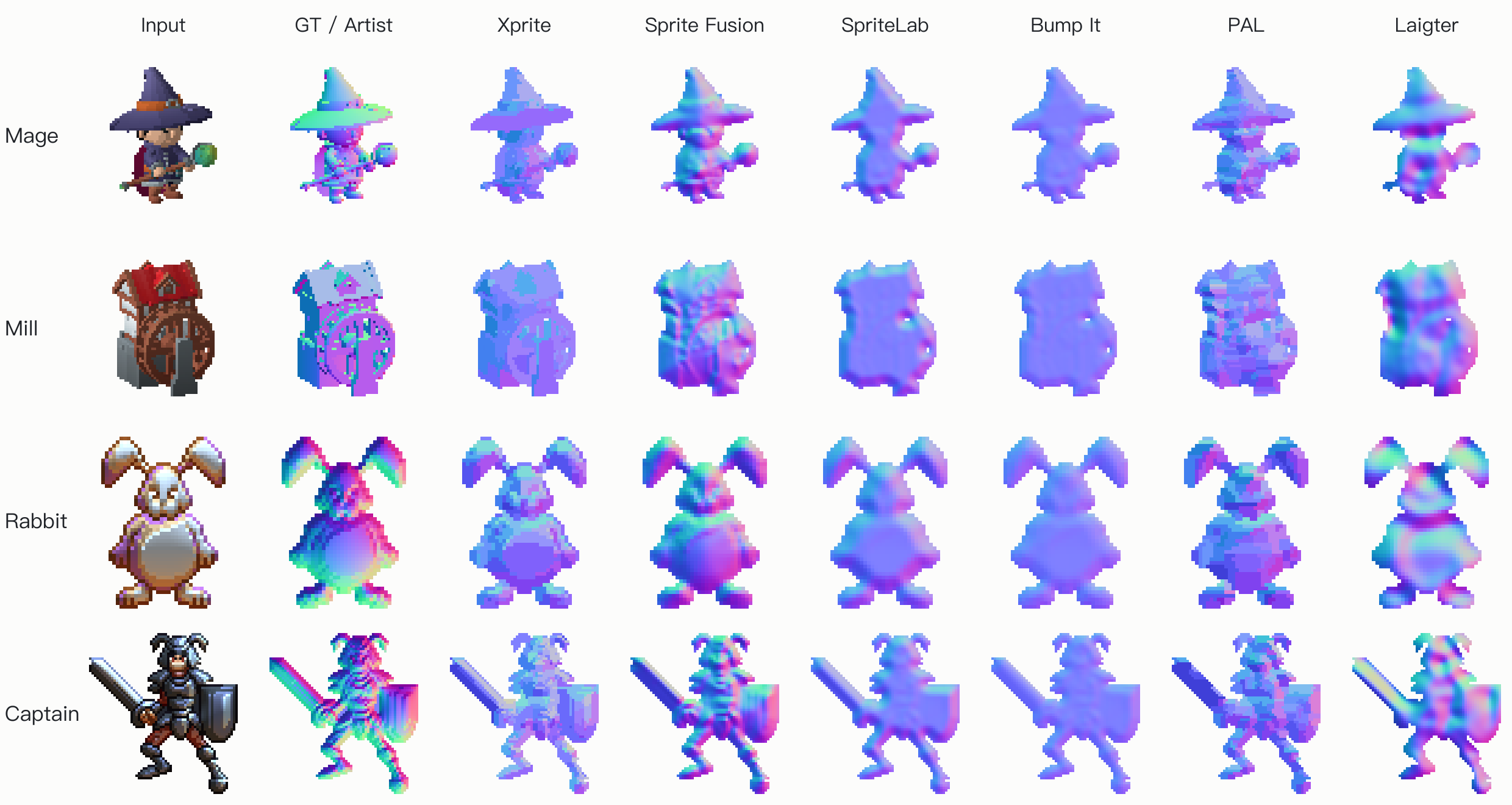
Before studying Pixel Art Lighter, let's look at how other normal-map generators work and where they fall short — to set a baseline and check whether PAL really is that much better (the author says he built it because every existing normal map he tried was unbearable).
| Tool | Approach | Form |
|---|---|---|
| Sprite Fusion Sprite Normals | Euclidean distance field dome + Oklab luminance, then gradient | Rust / WASM |
| SpriteLab | Chamfer-distance bevel + luminance + color-boundary grooves, blur then Sobel | Web |
| Bump It | Luminance as height, blended with outline bevel, masked blur then Sobel | Web |
| Laigter | Outline-distance bevel + emboss, default blur radii 6 and 10 | Desktop, GPL-3 |
| SpriteKiln | Per-connected-component quarter-circle dome by thickness + luminance detail, optional MoGe-2 AI normals | ComfyUI node |
| Normalizer | Procedural path adapted from Laigter, plus a DeepBump model running in the browser | Web / CLI |
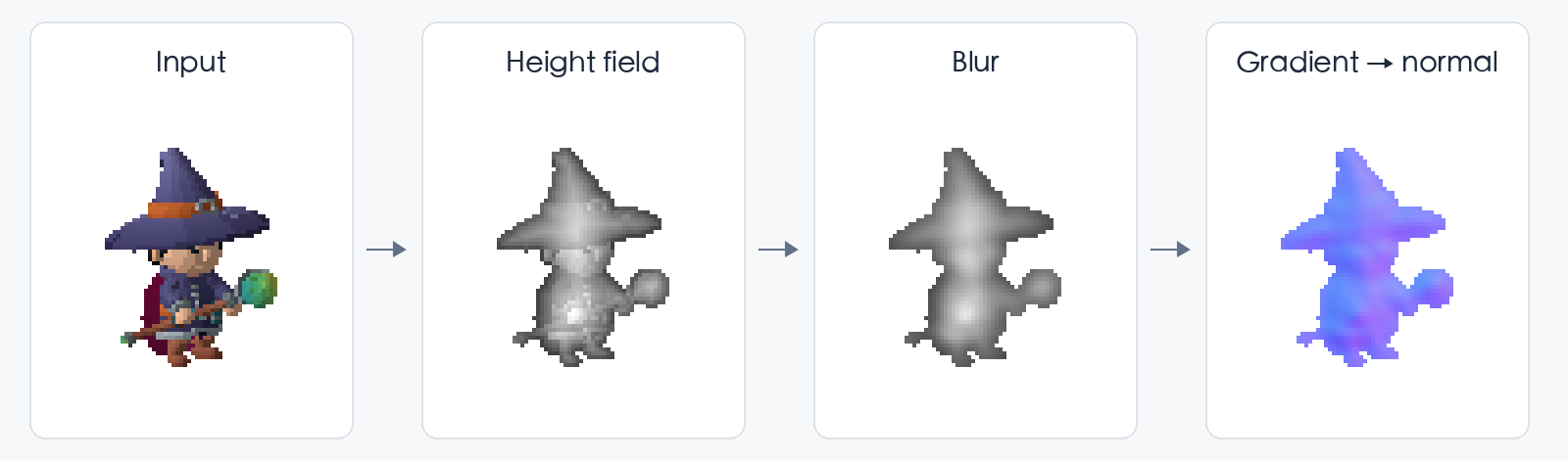
The recipe is largely the same: build a height field from luminance and outlines, blur it, then take local gradients as normals.
So the problems are similar too:
- Continuous normals: normals vary continuously per pixel, so a single color region ends up shaded with a gradient — like an inflated balloon.
- Luminance as height: like Pixel Art Lighter, they all fold luminance directly into height.
- Double lighting: the input already has painted-in light, so lighting it again from a new position stacks two lights on top of each other.
Among commercial tools, I looked at two:
- Sprite Lamp takes a different route: the artist paints the same sprite under several light positions, then normals are solved from that — essentially photometric stereo. It's the most accurate, but the artist has to paint several extra versions — which I definitely can't manage...
- SpriteLight says in its description that the default model "reads the painted light and shadow rather than guessing depth from brightness" — the same direction as my approach, but it's closed source, so the details aren't visible.
How Pixel Art Lighter works
PAL's core idea is to process per color region, which is what sets it apart from every other generator. It has seven steps in total:

- Same-color connected components: pixels with exactly the same color, connected horizontally or vertically, are grouped into a region.
- Height field: each pixel's height is the sum of two parts. One is the distance to the outline, square-rooted so the shape bulges upward toward the middle; the other is luminance — brighter means higher.
- Blur: under the default Object setting, the height field gets three passes of neighborhood smoothing.
- Per-pixel normals: take the gradient of the height field.
- Average per region, then quantize: each region averages its normals, then snaps to 8 directions × 4 tilt levels. A region gets exactly one facing direction.
- Split large regions into faces: regions large enough are grouped by whether their normals face up, down, left, or right; groups whose directions differ enough are split into separate faces.
- Outline absorbs neighbor colors: dark, thin regions are treated as outlines, and normals from adjacent regions are propagated inward; finally, fragments smaller than two pixels merge into their neighbors.
The magic is in step 5. With one facing direction per color region, lighting only changes at region boundaries — naturally aligned with the pixel grid.
Beyond normal generation, PAL also introduces the idea of a light mask: an extra mask image where darker regions receive less light.
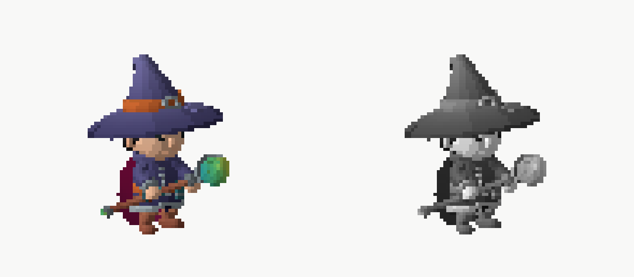
PAL's output is clearly better than its peers in pixel-art scenes, but it still has limitations:
- Luminance as height: most shading in pixel art is painted-in light; a bright area is a surface facing the lamp, not necessarily a taller one. More on this later.
- Exact same color only: anti-aliasing, dithering, and texture all shatter regions into pieces. The author also notes you should use assets with a clean palette.
- Thresholds in absolute pixels: at the default facet strength, a region needs at least 142 pixels to be split. A 32px sprite can barely split at all, while a 96px one over-splits.
My approach
Lighting-angle estimation
The main problem I wanted to solve is "brightness ≠ height": most sprites carry highlights and shadows to convey volume, and when that color variation is misread as height, the normals point the wrong way, producing a gradient on what should be a flat area.
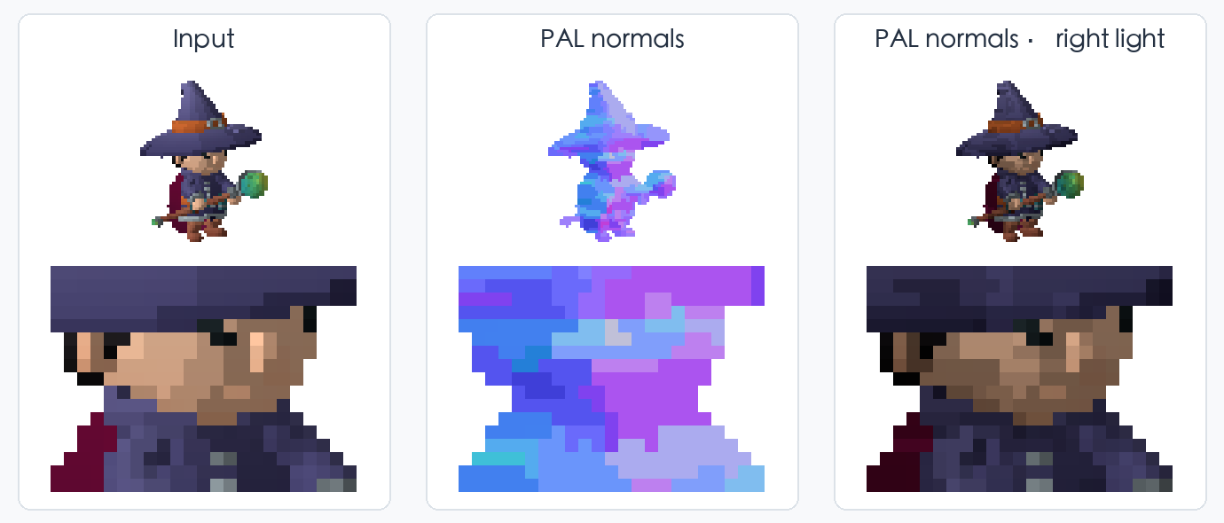
This reminded me of the active noise-cancelling headphones I use: they extract the noise's frequency band and overlay an opposite-phase wave to cancel it. Could an image do the same — extract the lighting direction to get more accurate normals?
If you know where the light comes from, you get a different interpretation: brightness mainly says this pixel faces the lamp. Concretely:
- Reduce luminance's weight in the height field by 1 − the influence factor (60% by default).
- Compute how much brighter each pixel is than its surroundings (box average, radius scales with image size), and push the normal toward the light direction proportional to that difference.
Where does the light direction come from? Ideally it's inferred automatically from the image; failing that, a slider works — tools like this usually need manual tuning anyway for the best result.
Automatic estimation
The outline is the most reliable clue: whatever the image depicts, surfaces near the silhouette roughly face outward. So we only look at the band within 4 pixels of the outline, approximate those pixels' normals with the outline distance field, and check which light direction best explains their shading.
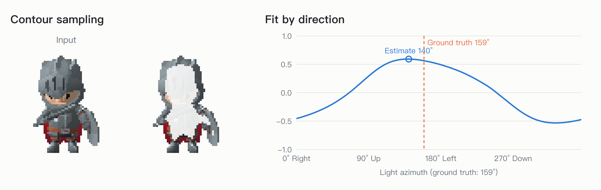
- Group by "connected component × chroma", subtracting each group's mean brightness so clothing-vs-skin albedo differences aren't read as lighting.
- Over 72 azimuths × 3 elevations, compute the correlation between the Lambert prediction and actual brightness; take the best direction.
- Bail when unsure: correlation below 0.3, failure to separate from the opposite direction, more than 45° of direction drift when the image is quartered and each quarter removed in turn, or a standalone component disagreeing with the global direction by more than 75° — all count as "no estimate".
- When correlation sits between 0.3 and 0.45, the influence factor is scaled down proportionally.
Manual angle
Automatic estimation will sometimes be unsure. But most of the time, either I'm the artist and already know where the light is, or I can tell at a glance — entering a single angle is far easier.
The first case is basically having the ground truth. But if I'm not the artist and my guess is off, how tolerant is the method? We want decent results within a reasonable error range.
I tested the error across all scenes over the full 360°. Results:
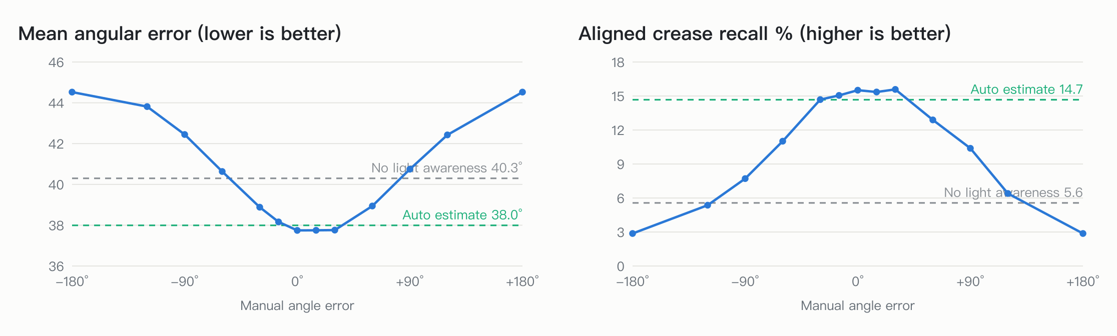
- Within ±15°, results are almost identical to the exact angle.
- At ±30°, still on par with automatic estimation.
- By ±90°, it's worse than having no lighting awareness at all.
So as long as you roughly get the direction right, you capture most of the benefit — a very cheap win.
De-lighting the input
This addresses the conflict between the input's painted-in light and the re-rendered light. Suppose the original was lit left-to-right (bright left, dark right). Even with correct normals, when the new light comes from the right — producing dark-left/bright-right shading — the stacked result often stays bright-left/dark-right.
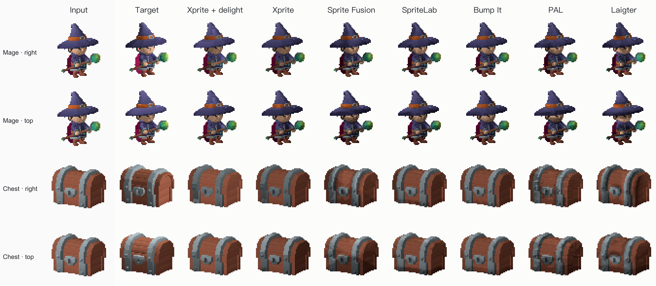
In the chest scene, the original is lit from the left, so the right side carries heavy shadow. Overlaying a right-to-left dynamic light still fails to brighten it.
So I added a de-lighting step: using the generated normals and the estimated light direction, assume the input was painted as "15% ambient + a directional light at 45° elevation", subtract that light, then apply the new one. The result is noticeably better — the right side actually lights up.
In practice, though, de-lighting can flatten the color range, so it's an experimental feature that's still being tuned.
Lab color-distance clustering
PAL requires neighboring pixels to have byte-exact identical RGB to join the same cluster, so it needs a fairly clean palette. Complex colors or anti-aliasing fragment it into many tiny regions.
I switched to region growing in CIELAB: a neighbor joins the same region if its ΔE from the adjacent pixel is at most 6, from the seed at most 10, and the alpha difference is under 48.

In the evaluation set, the knight went from 1090 regions to 191, and the chest from 1234 to 57. Regions become "faces" again, which makes the later faceting and quantization meaningful.
Adaptive faceting thresholds
- The minimum face area scales with foreground area (relative to a 64 × 64 baseline, at most 2×), and the grouping support threshold scales with the square root of region area — so small sprites can still split into faces.
- The outline-bulge curve transitions from square-root to linear as the image grows, preserving crease directions better on larger sprites.
Benchmark
Evaluation set design
With this many changes, a benchmark is a must. But this niche is small — after looking around, there are basically no public datasets:
- pixel-art-normal-maps has over 14,000 pairs, but the target normals are quantized and outline-processed — stylized normals, not ground truth.
- Some OpenGameArt packs ship normal maps, but those normals were auto-generated by Sprite DLight.
Evaluating against generated normals only measures "how much it resembles another tool". So I fell back on the dumbest reliable method: render 3D models into pixel art and take the ground truth straight from the model.
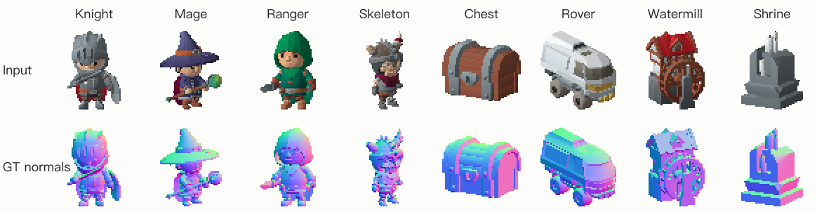
- 8 CC0 KayKit models: knight, mage, ranger, skeleton warrior, chest, rover, water mill, shrine.
- 2 views per model × 4 native sizes (32, 48, 64, 96 px) — 64 cases in total.
- Orthographic rasterization with per-pixel depth testing and no anti-aliasing. Ground-truth normals are interpolated vertex normals inside the visible triangle; base color comes from the model's texture.
- Inputs are lit from the left (azimuth 159°, elevation 29°), with shading quantized into five bands — close to cel-style pixel art.
- Four additional light positions (right, top, bottom, front) are rendered as re-lighting targets.
Then the metrics. Note that we don't aim for "generated normal = ground-truth normal" (that doesn't fit pixel-art scenes), so the metrics focus on creases and angular error:
| Metric | What it measures |
|---|---|
| Crease AP | Rank all adjacent pixel pairs by predicted normal jump; check how early the true "creases" (jumps ≥ 30°) rank |
| Crease recall (direction-matched) | At true crease locations, the prediction also has a ≥ 30° jump in a consistent direction |
| Mean angular error | Angle between predicted and ground-truth normals |
| Re-light RGB MAE | Re-light the input to the four new positions with predicted normals and compare pixel-by-pixel against the targets |
Results
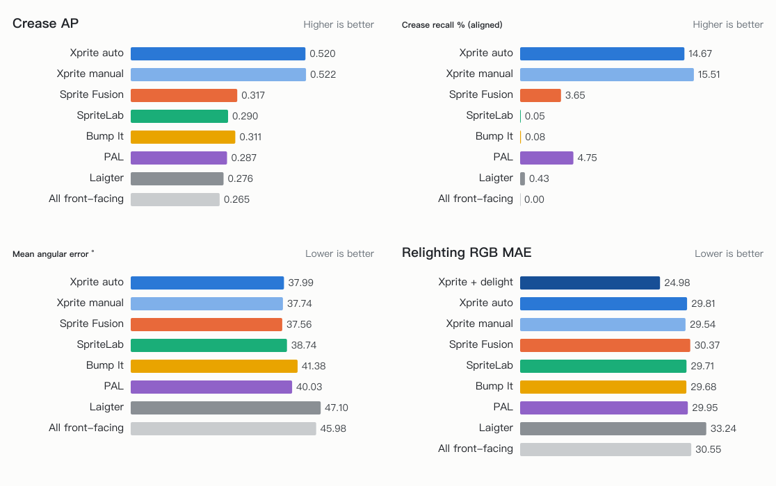
| Method | Crease AP ↑ | Crease recall % ↑ | False creases % ↓ | Mean angular error ° ↓ |
|---|---|---|---|---|
| Xprite (auto angle) | 0.520 | 14.67 | 1.19 | 37.99 |
| Xprite (manual angle, 160°) | 0.522 | 15.51 | 1.20 | 37.74 |
| Sprite Fusion | 0.317 | 3.65 | 2.76 | 37.56 |
| SpriteLab | 0.290 | 0.05 | 0.04 | 38.74 |
| Bump It | 0.311 | 0.08 | 0.01 | 41.38 |
| Pixel Art Lighter (original) | 0.287 | 4.75 | 4.42 | 40.03 |
| Laigter | 0.276 | 0.43 | 0.95 | 47.10 |
A note on the metrics that look less flattering:
- False creases: SpriteLab and Bump It are near zero because they barely produce any creases — the denominator itself is small.
- Mean angular error: since Xprite and PAL both target pixel-art lighting and cluster normals into flat regions, comparing directly against continuous ground-truth normals carries an inherent theoretical disadvantage.